|
|
|
|
|


I'm Online Chat Now
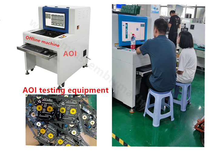
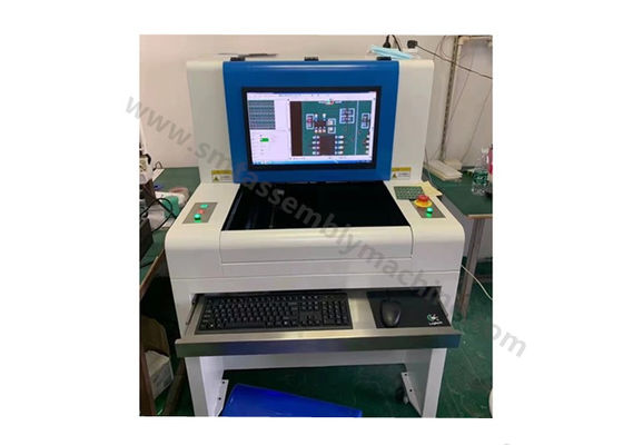
AOI Application Inspection SMT Assembly Machine Surface Mount Device Panasonic
|
Product Details:
Payment & Shipping Terms:
|

Detailed Product Description
| Product Name: | AOI Testing Equipment | Model: | SZ-X1 |
|---|---|---|---|
| Camera: | Camera Smart Digital Full Color | Thickness Range: | 0.6~5.0mm |
| Maximum Maximum PCBA Weight: | 3.1kg Approximately | Condition: | New |
| High Light: | AOI Inspection SMT Assembly Machine,AOI testing SMT Assembly Machine,Panasonic Surface Mount Device |
||
AOI application inspection SMT Assembly Machine surface mount device Panasonic
SMT patches and inspection equipment
CAD import
CAD is automatically imported by higher-level software
After the CAD data is imported, click Reset Fields to reset the names of each field
1) Component Location: The name of the component location of the standard component in the actual coordinate system.
2) X: The abscissa of the standard component in the mechanical coordinate system.SMT Pick And Place Machine
3) Y: The ordinate of the standard component in the mechanical coordinate system.
4) Angle: The angle of the standard component in the mechanical coordinate system.
5) Part number: corresponding to the part number standard in the factory, an important parameter of automatic component linking.
6) Length: Component length.
7) Width: Component width.
After setting the CAD data column field names, select "Next" to convert the data according to the actual situation.
(Generally default is sufficient)AOI Inspection Machine
Then select Next to bring up the component image image
Image area description: The above image is a renderings of component mirroring, through this diagram, compared with the actual component image, the CAD data and the data component data correspond.
Toolbar:
1) Rotate 90 degrees clockwise: The mirror image is rotated 90 degrees clockwise.
2) Rotate 90 degrees counterclockwise: The mirror image is rotated 90 degrees counterclockwise.
3) Rotate 180 degrees: The mirror image is rotated 180 degrees clockwise.
4) Horizontal mirroring: Mirroring the image horizontally mirroring the image.
5) Vertical mirroring: A vertically mirrored image of the mirrored image.
6) Previous step: Go back to the previous step.SMT Assembly Machine
7) Finish: After the component image image is adjusted, load the CAD data into the program.
8) Automatic linking according to common standards: When selected, the data will be automatically linked to the standard data of the common standard diagram.
[Note] For larger PCB boards, the coordinate positions of all components can be aligned by two components that are far apart (diagonally) by doing so :
Click [Lock] (the button name changes to [Set Identification Point]), align the center of the "ten" in the FOV diagram with the center of the component, then click [Set Identification Point] in the CAD import window, and then set another identification point diagonally in the same way. After this step, there is no need to use [global offset] to make the component position accurate.
Switch to the thumbnail window when the CAD import is complete:
Function parameter
| SZ-X1 Product Specification | ||
|
Test items |
Programming mode | CAD data impor t automatically for component librar y |
|
After reflux fuenace |
Component: Wrong par ts,missing par ts,polarity,deviation,monument,reversal,damage,lc bending,doreign matter, etc Solder joints:less tin,more tin,tin hole,bridging,tin coating,false tin,tin bead,etc |
|
| Minimum paet test | Theoigh the resolution the minimum measuradle is 03015(01005)chip&0.3 pitch IC | |
|
After Wave Soldering |
Less tin,more tin,tin hole,false tin,bridge, tin psckage,tin beda,etc | |
![]()
Contact Details
Shenzhen Wanbo Hi-Tech Co., Ltd.
Contact Person: Leo Huang
Tel: 18665307937
Send your inquiry directly to us
More AOI Inspection Machine
-
AOI SMT Inspection Machine Full Color CCD Camera Networkable Remote Operation
-
AOI Surface Mount Machine SZ-X1 0201 0402 0805 PCB Inspection System
-
AOI X1 Offline Inspection SMT Pick And Place Equipment SMT Assembly Machine
-
AOI SZ-X3 Versatile optical inspection machine For Measure Welding Effect Of DIP Silver Feet
-
Offline Versatile AOI Inspection Machine SZ-X3 Software Function Image Comparison High Pass Rate
-
Offline Machine AOI SZ-X3 Post Welding Electronic Board Short Circuit Check